Composite Solar Vehicle Chassis
As the current Mechanical Lead of the Illini Solar Car team, I oversee many high-level decisions regarding the vehicle, but the component that I worked most on was the composite chassis for our upcoming vehicle.
Stiffness, strength, and low weight are the critical driving constraints for this chassis. An efficient solar car is as light as possible, but needs to be stiff enough to support its own weight and any dynamic loads imparted by the suspension, and strong enough to keep the driver safe in an accident.
I designed our upcoming vehicle's structural chassis. A key feature is the a unique single-piece carbon fiber monocoque construction commonly seen in F1 cars, with various carbon fiber sandwich panels which support the auxilary components of the vehicle.
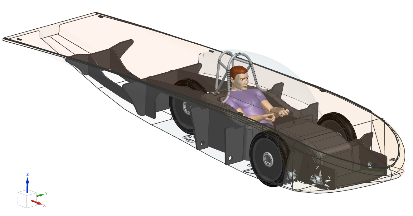
Siemens NX CAD model of the structure within the car.
I am currently still working on the design and soon going to be running more FEA static structural analysis on the chassis and improving the design, so I hope to update the page soon when I have more work to show off!
Monocoque
Design
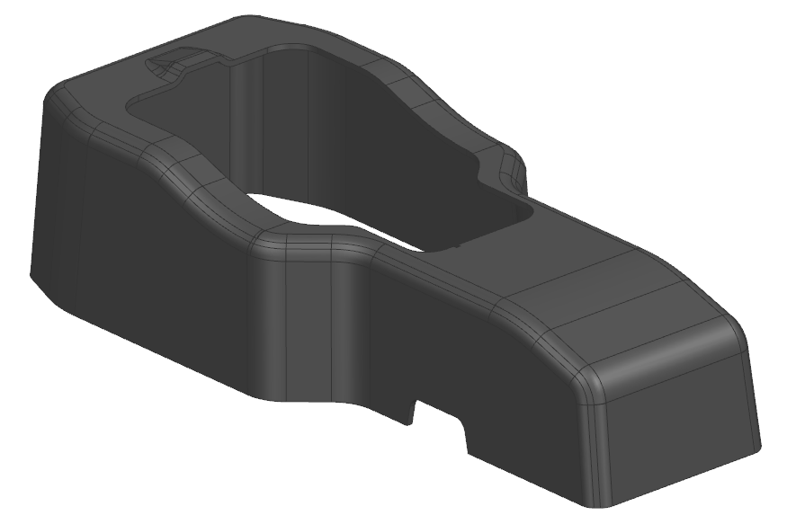
Single-piece carbon fiber monocoque. All critical components of the vehicle such as suspension, and chassis panels connect to this central rigid structure, in which the driver also sits.
As mentioned earlier, the monocoque is the key feature of my chassis design.
The monocoque is constructed as one single piece on top of a large mold. The material is a laminate structure made of layers of carbon fiber sandwiching a hollow aluminum honeycomb core. This aluminum honeycomb core lends greatly increased stiffness to the structure by separating the rigid carbon fiber "skin" like an I beam.
The design of this structure also takes advantage of the molded geometry, allowing complex curves and shapes. The entire monocoque is designed with generous fillet radii in order to minimize stress concentration and better distribute stress throughout the structure. Careful thought is also put into shape of the structure to increase stiffness and also ensure it is manufacturable via the molding process and can be demolded. A draft angle on the structure helps with demolding specifically. A flange is also added around the driver region to increase stiffness and prevent "caving-in" of the structure.
Analysis
In order to pass regulations, our vehicle's structure must pass certain loading scenarios. One example is shown below, in which a "5g load" (5x the weight of the vehicle) is applied to the side next to the driver.
To generate valid analysis results which would be applicable to reality, I utilized the Ansys Composite PrepPost (ACP) tool in order to properly define the fiber directions, plys, and laminate stackups which we would constuct the monocoque out of.
I am still in the progress of running more in-depth analysis, but from this first preliminary analysis, it reveals that there are high stresses at the bottom of the monocoque, and there is also a stress concentration near the front of the driver cut-out. The stress near the bottom is important to note, as the bottom is bonded to the monocoque, since it cannot be molded all as one piece. It will be critical to have a solid glue bond for the bottom for its construction.
Our team will also be looking into collecting material properties such as ultimate strength and elastic modulus specifically for composite materials that we create. This is important, as composite strength can depend heavily on manufacturing process, so we need to validate the model by using accurate material properties from our own testing.
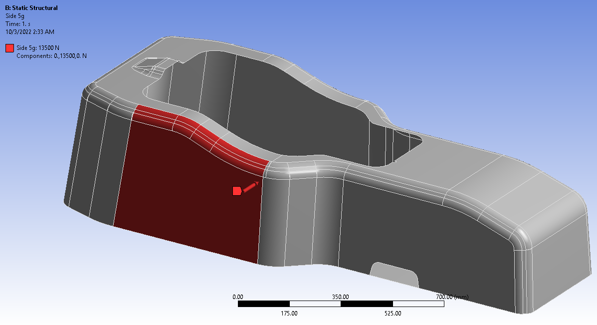
Monocoque side-loading setup
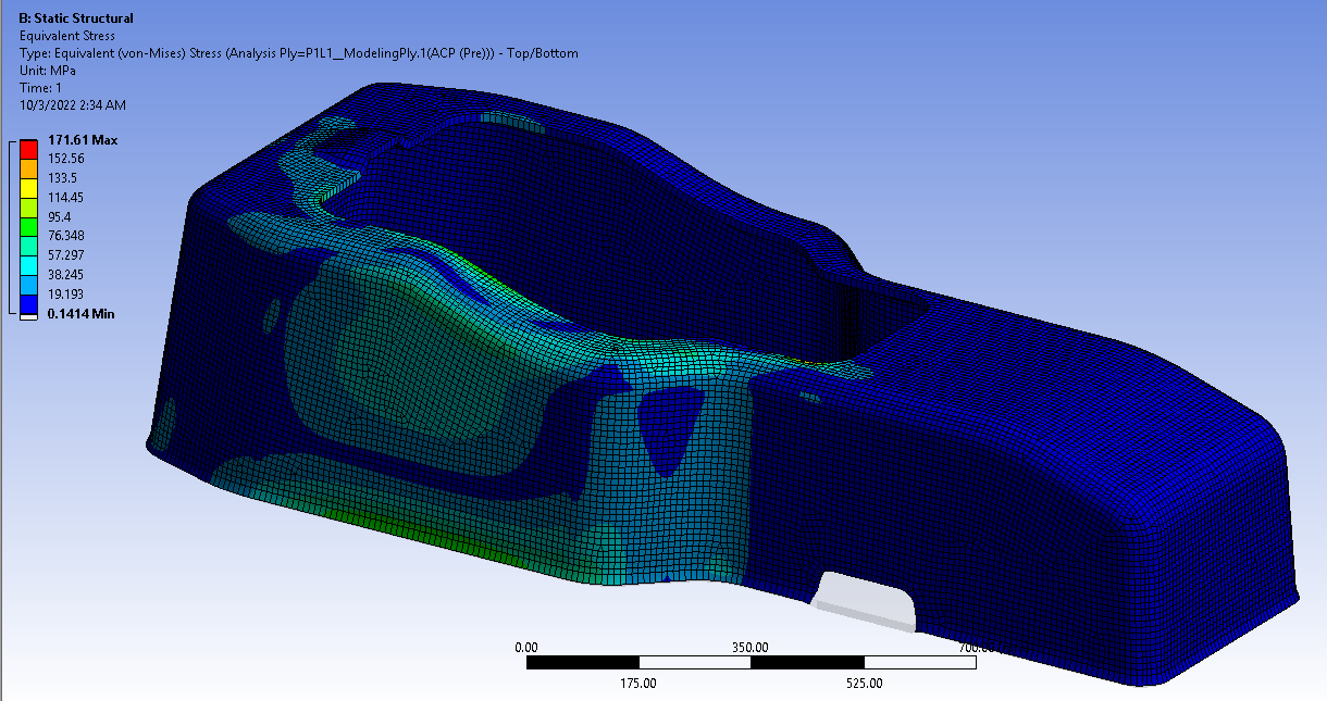
Von-Mises stress plot of applied load