FIRST Tech Challenge Robot
FIRST Tech Challenge (FTC) is a high school robotics competition in which students construct robots that move around a 12' x 12' playing field and manipulate game elements to score points. A match is played in a 2 vs 2 format with two teams forming an "alliance" to play against another alliance. The first 30 seconds of the match consist of an autonomous period where the robots must complete tasks on their own, and then 2 more minutes where the robot can be driven and commanded around the field. I've been the team leader for FTC team 9866 VIRUS for 5 years, and actively contributed to the CAD, building, and programming of the robot. This page shows off what I and the team accomplished in our 5th year competing.
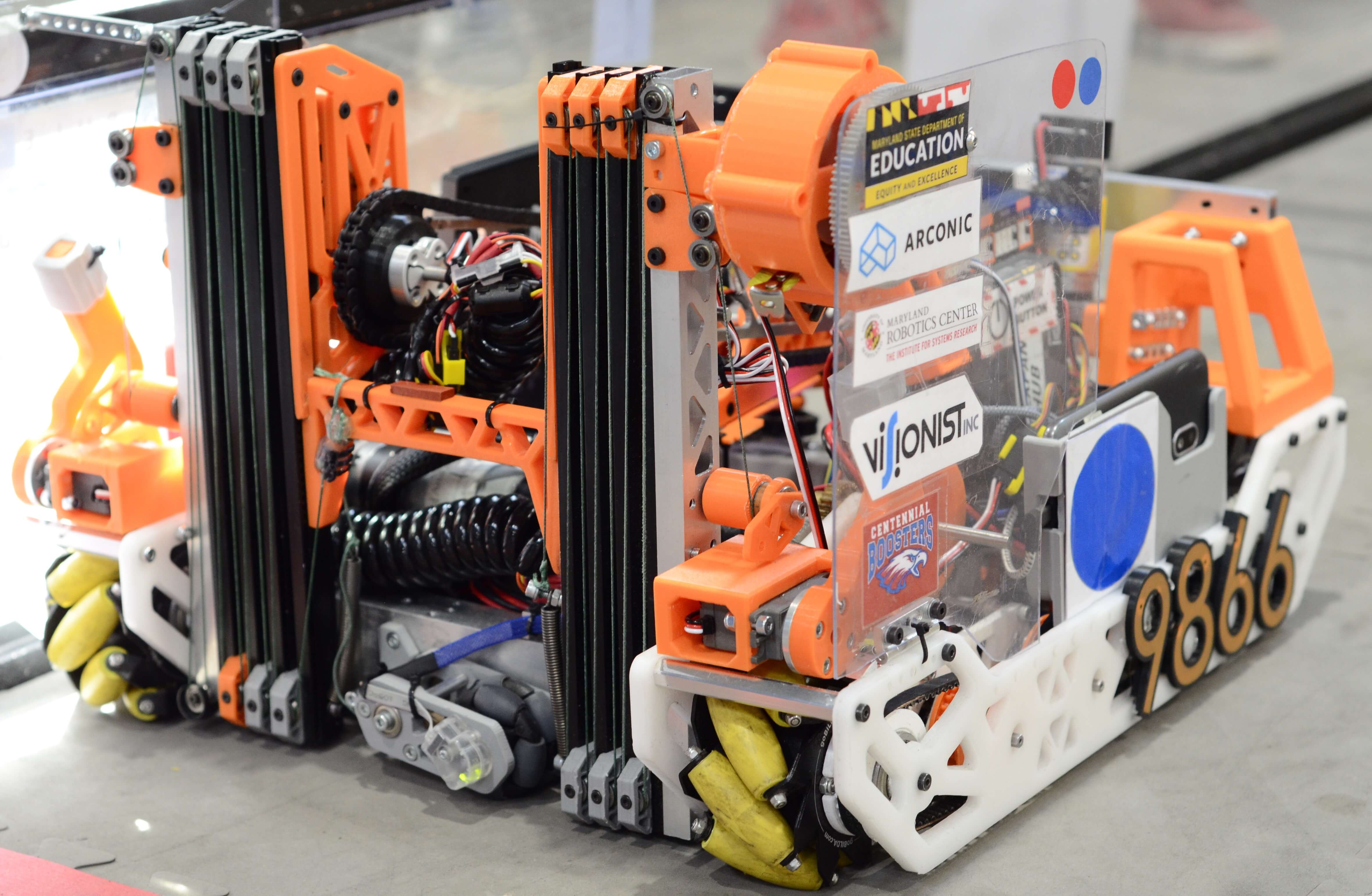
A video of our performance at the state competition featuring commentary from me and my teammates. (Our robot is the white and orange robot #9866)
2020-2021 "Skystone" Challenge Overview
This year's main objective was transporting "stones" (giant yellow bricks) onto a foundation and stacking them as high as possible. In the initial autonomous period, tasks included scanning a line of stones to find the special "skystones" and placing them onto the foundation, dragging the foundation into a corner of the field, and parking under a structure in the center of the field. Once the driver controller period begins, the alliances work together to stack as many blocks onto the foundation as high as possible, and at the end of the match, the teams must place a "capstone" at the top of their tower, drag the foundation with the stones on it out of the corner of the field, and park in that corner for extra points.
Robot Overview
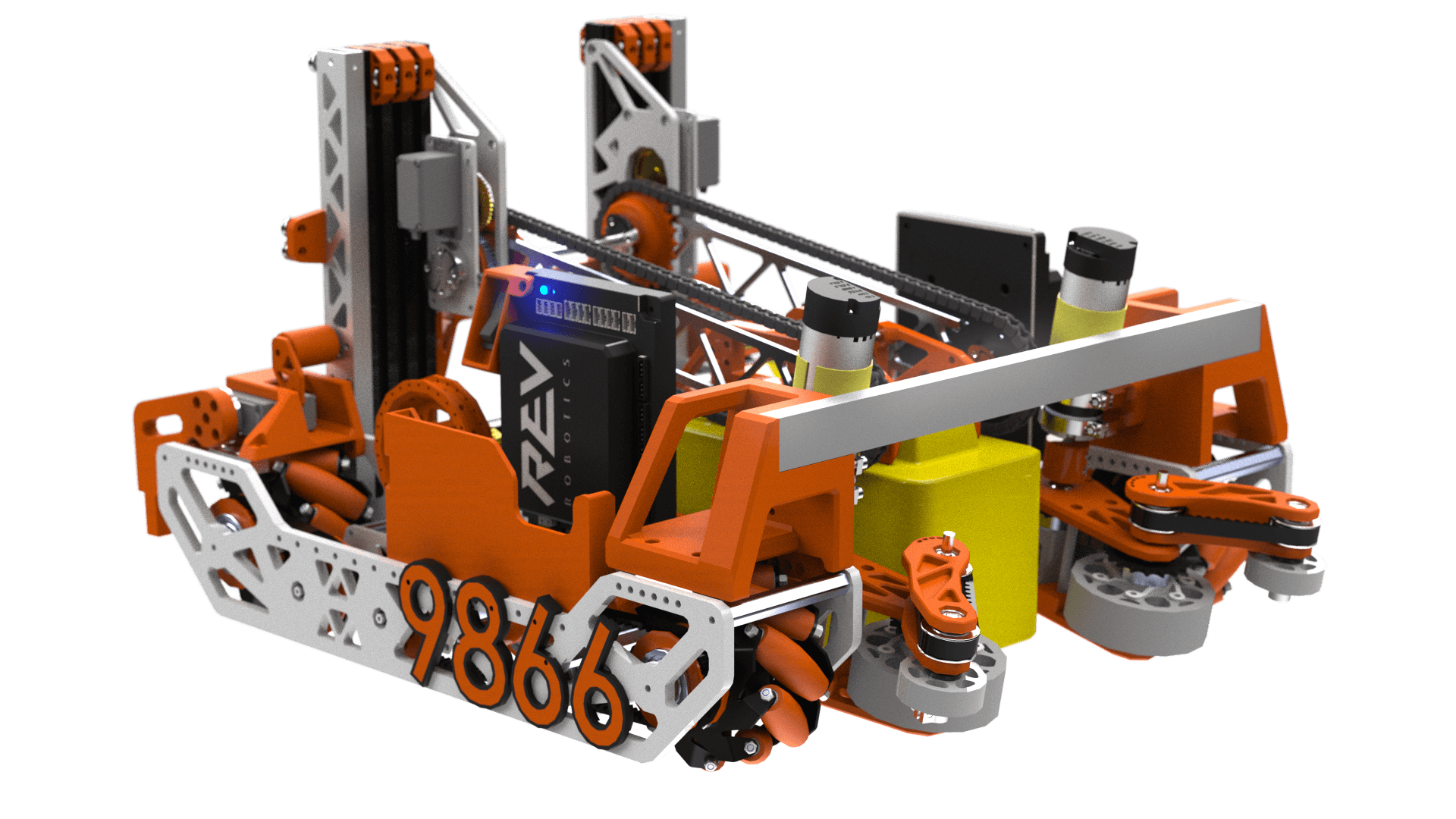
Our robot consists of a couple major sub-systems. The drivetrain is the mobile base of the robot and utilizes mecanum wheels that allow the robot to drive sideways for extra agility. Attached to the front of the drivetrain is the intake, which consists of spinning wheels that can funnel stones into the robot. Next, the stone is grabbed by an arm that grabs the stone and rotates 180 degrees and places the stone behind the robot onto the foundation. The arm is mounted to a set of vertically extending slides using a pulley system that allow us to stack up to 9 blocks tall. Lastly, a foundation dragger mechanism consists of 2 fingers that allow us to grip the foundation, and 3 dead wheels make up the odometry subsystem of our robot that can track our robot's position and heading. The CAD for this robot was created in Solidworks, and there is a link below to the CAD assembly. In addition, the robot features many custom 3D printed and CNC machined parts. I did not design the entire robot, but I will cover the parts that I worked closely on in the following sections.
Drivetrain
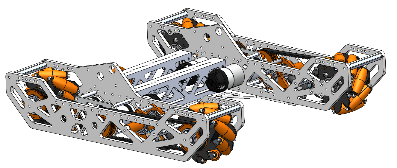
The robot's drivetrain acts as a mobile base that the rest of the robot is built on top of. I designed and machined most of the drivetrain's structure out of 1/4" Delrin plate and 2 square tubes that connect the two halves together. The drivetrain was constructed with a large amount of space in the front in order to accommodate room for an intake and stones that come into the robot. There are 4 motors that are connected via timing belts to the mecanum wheels. These wheels are special because they allow the robot to move sideways (like a crab). We chose these wheels because they aided in lining up the robot to stack the blocks, and we chose timing belt for its low backlash. Lastly, the drivetrain includes odometry dead wheels that track the robot's position. (More on that in the odometry subsystem section) Overall, I designed the drivetrain to be compact and save as much space as possible for the other mechanisms and utilized many custom manufactured and machined parts to make this happen.
Vertical Extension
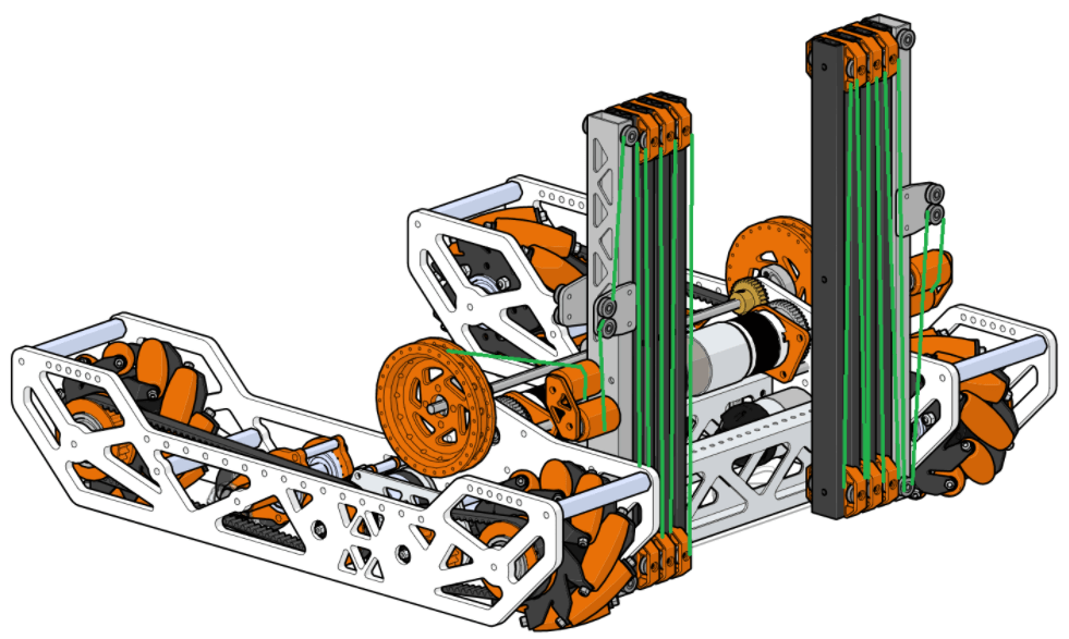
In order to stack the stones, we needed to be able to reach up to the top of the stack, but the robot also needed to be low enough to pass under the bridge in the center of the field. The solution was a set of extending "slides" powered by a rope and pulley system allowing us to reach to the top of the tower and come back down to be prepared to grab the next stone to stack. The slides are designed for drawers, but we stacked them back to back and repurposed them to be used with our robot. We also backed with a custom machined aluminum square tube in order to give them some more rigidity because they were a bit thin. Lastly, I designed a system of pullies to raise and lower the slides. I chose a large pulley diameter and a fast gear ratio (12:1) with two motors in order to quickly raise and lower the slides, minimizing the time wasted. In addition, a long shaft running between the two pullies keeps the two pullies mechanically in sync with one another, and allows the two motors to work together to raise and lower the slides, as opposed to having one separate motor operate the retract stringing and another motor operating the extension stringing.
Intake
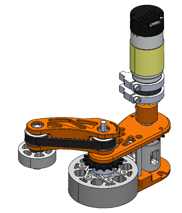
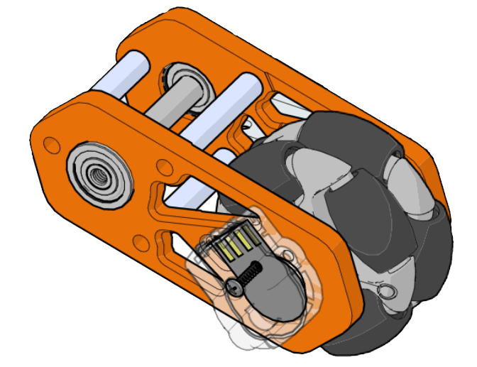
One of the primary challenges was being able to effectively take control of the stones, which were placed onto the field in certain locations. We wanted to be able to grab a stone from any angle as reliably as possibly in order to minimize the amount of time needed to grab a stone. The intake that we designed used a set of grippy spinning wheels in order to grab the stones and funnel them into the robot. One of two intake modules is shown on the right. The entire intake module is designed to pivot about an axis in order to conform to the stone entering the robot, and although it is not shown, is sprung in order to allow the module to somewhat maintain its position. In addition, the entire intake is rotated slightly upwards so that the stones are launched up and into the robot, allowing it to clear the gap between the bottom of the robot and the floor. The largest wheel is powered by the same axle that the module pivots on via a chain, and the smaller wheel uses a belt.
The smaller additional belt driven wheel was added later to help "funnel" the stones into the center of the robot and increase the effectiveness of the intake. One of the features is its "bean" shape, which accommodates for the corner of the stone getting caught between the two wheels, and allows the belt to also help pull the stone into the robot.
Odometry
A special feature of our robot this year was a set of 3 dead wheels that we used in order to keep track of our robot's position in the autonomous mode. The "odometry modules" (pictured on the right) were designed so that our programmers wouldn't have to worry about slippage between the wheels and the ground in the motor encoder readings. They make use of a special magnetic encoder that is resilient to dust collecting near the sensor, and an omni wheel mounted on the shaft of the encoder. The entire module pivots about an axis similar to the intake and is also sprung using a rubber band to push into the ground and give the wheel enough grip to accurately track robot movement.
Team Awards
That year, our team won numerous awards at the Maryland State competition including 1st place "Design Award" (given to teams incorporating industrial design into their robot), Finalist Alliance Captain (We captained the "runner up" alliance), ranked 1st during the qualification matches in our division, and advanced to the world championship in Detroit (unfortunately cancelled due to COVID-19).
More Details can be found here
Personal Contribution
Because I worked on a team of 8, the robot is not entirely my own work, but the drivetrain, intake, slides, and odometry subsystems mentioned above were all mostly designed by me. In addition, as team leader I helped assign roles and delegate specific jobs/tasks to be done.
Links
Engineering Notebook Building Section
Engineering Notebook Design Section
Robot GrabCAD