Moonshot V2- 1lb Combat Robot
Moonshot V2 was designed to meet the same goals as the original: hit hard and be extremely mobile. It achieves these same goals while making improvements on all subsystems (drive, weapon, and chassis) which were only possible with a complete robot archetechture revamp.
See my previous write up on V1 for more context!
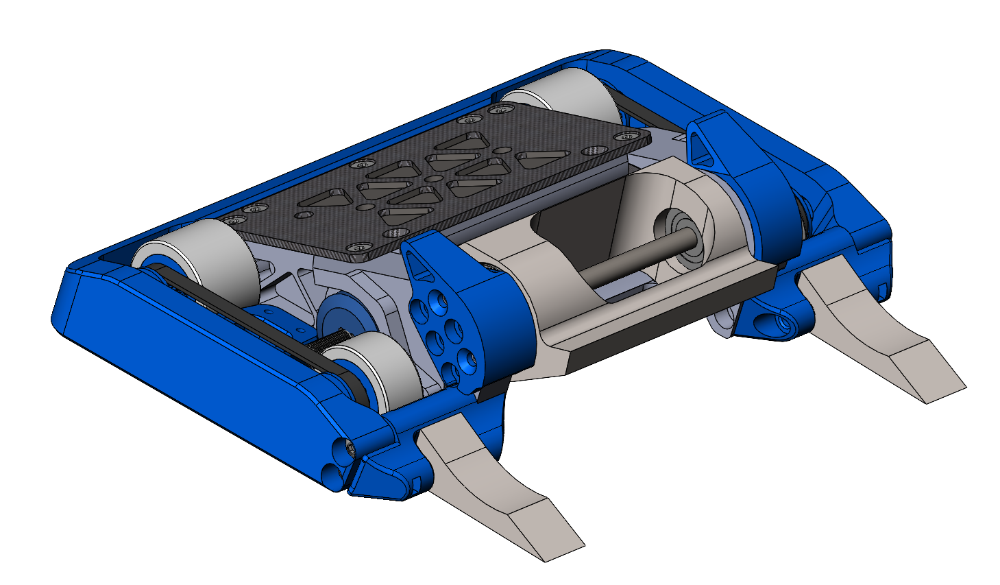
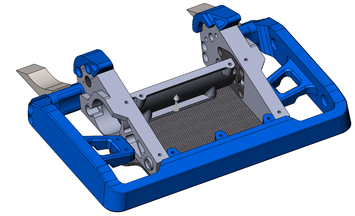
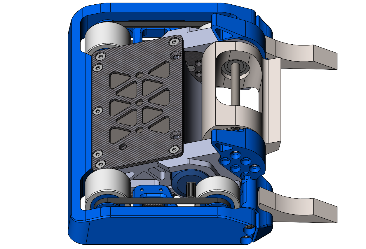
CAD model of Moonshot v2
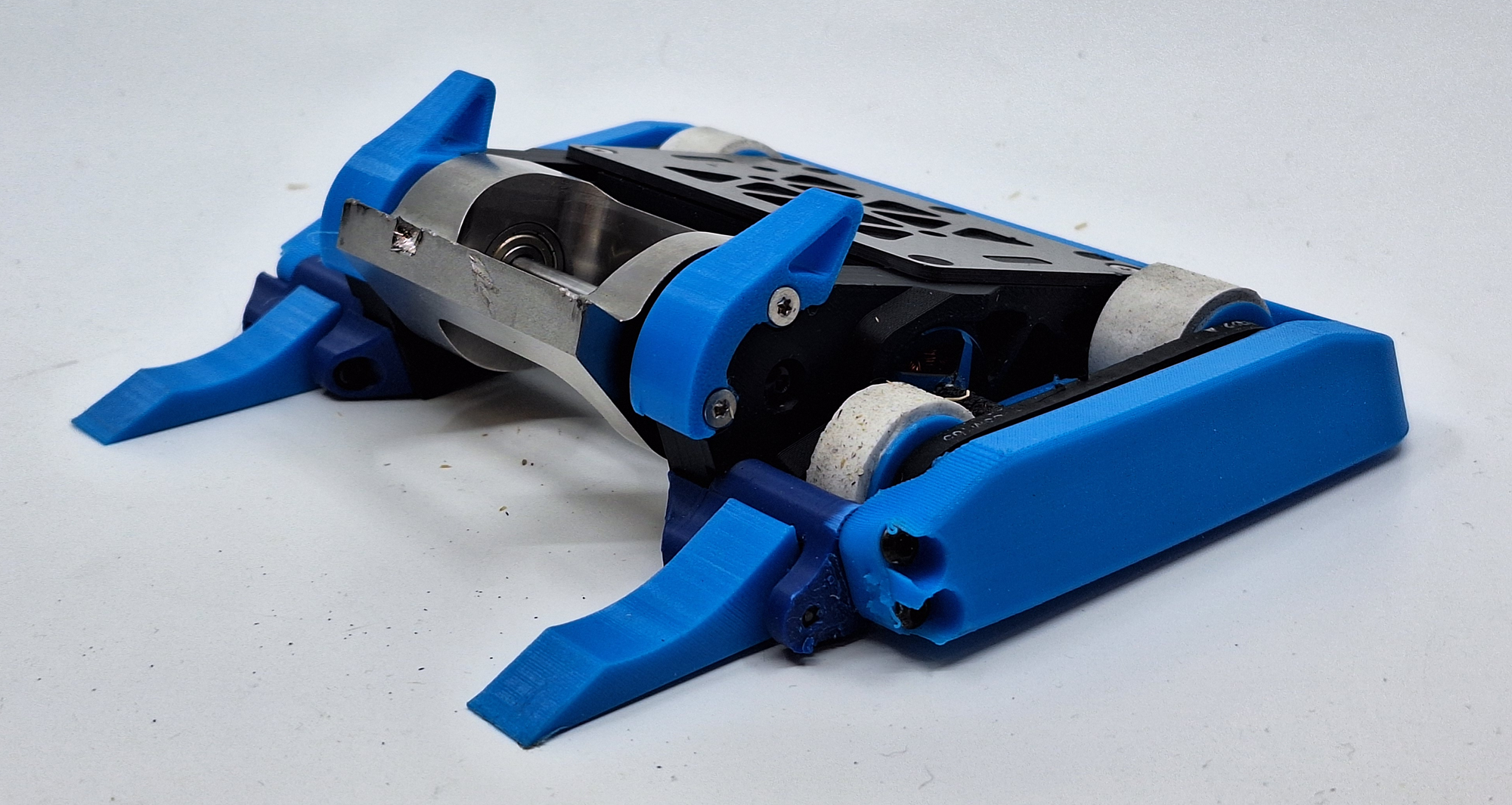
Moonshot v2 put together
A featured fight from the 2024 MRCA Finals
Design Narrative
Weapon System Improvements
Moonshot's previous weapon system featured an aluminum drum with screw teeth which was press-fit onto an off the shelf brushless motor. There were several issues with this previous implementation.
1. Screw impactors would get damaged and even shear off, throwing off the drum's balance
2. Damage potential was low, the aluminum drum does not pack as much energy as a denser material, and the screw teeth have limited effectiveness
3. No positive retention between the weapon and meant the weapon could fly out of the bot with significant deformation (yes this has happened before!)
4. Due to not having a continuious shaft between the two ends of the drum, both ends needed to be kept in alignment for smooth rotation.
A missing screw impactor that sheared off on the moonshot v1 weapon
For Moonshot V2's first iteration, I focused on solving problem 1 and 2. The weapon system was kept largely the same, but with a new hardened 4340 steel weapon. This was made possible by no longer being a college student and ahving a full time job + salary!
Weapon was bent after a big impact
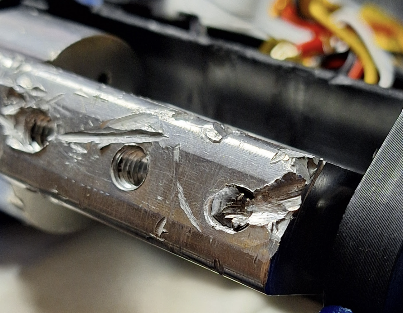
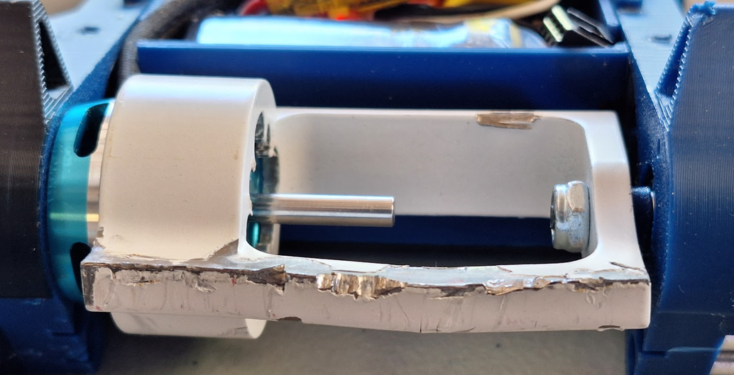
I got feedback quickly after the first competition. The steel weapon packed a punch, but the increased damage and increased material hardness meant that I was now imparting much higher impact loads onto my weapon motor, which resulted in shattered rotor magnets.
Additionally, the weapon was bent in a big impact! Due to steel being almost 3x the density of aluminum, the new drum was much thinner and appearently did not have enough sectional area to resist bending. I suspect the fact that the alumiunum bar was able to locally gouge and deform also helped prevent significant deformation like shown.
Weapon was bent after a big impact
Lastly, I was having a tough time controling the bot. It would vibrate enough to start moving on its own with no input. At the time, I thought this was due to misalignment between the motor and the shaft support on the end (more on this later!)
I needed to solve the issues I found and also address some of the previous issues that had crept up before. The solution that I settled on was to commit to a "hub-motor" design.
This design integrates the motor itself into the weapon drum in a way that attempts to isolate the motor components from direct loading. This is achieved by doing the following:
1: Select a donor motor (2207 brushless drone motor in my case) and seperate the rotor and stator
2: Extract the magnet ring from the rotor, and embed it into the weapon drum
3: Design a shaft + bearing system that mounts the weapon, but allow the stator to sit inside the weapon, isolated from direct loading.
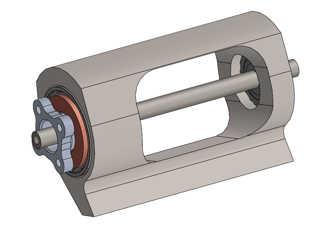
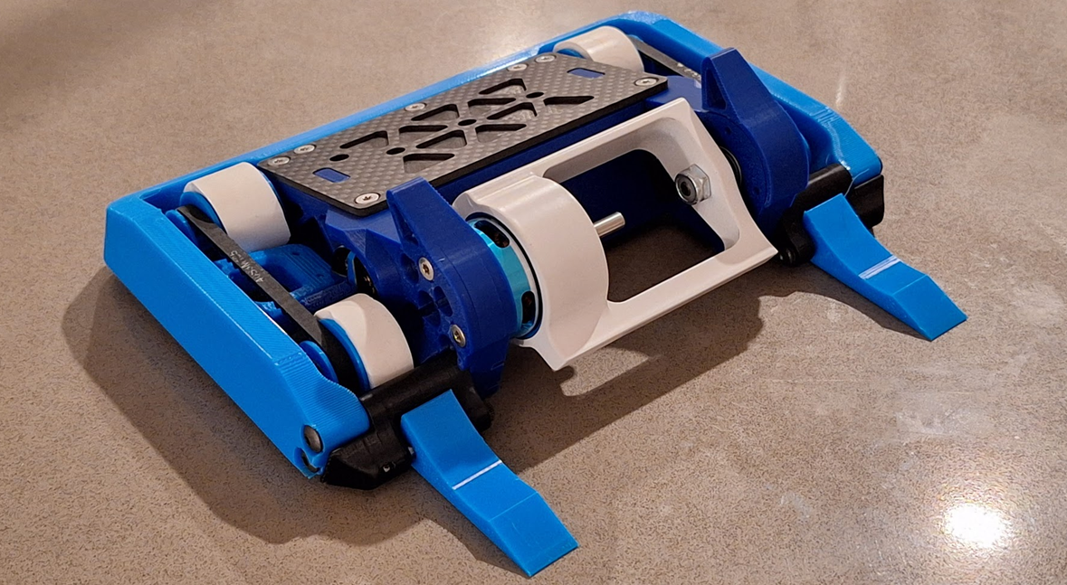
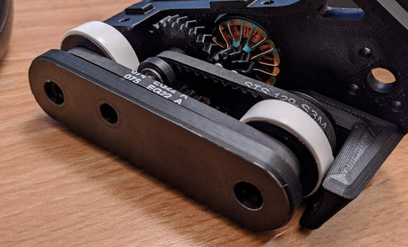
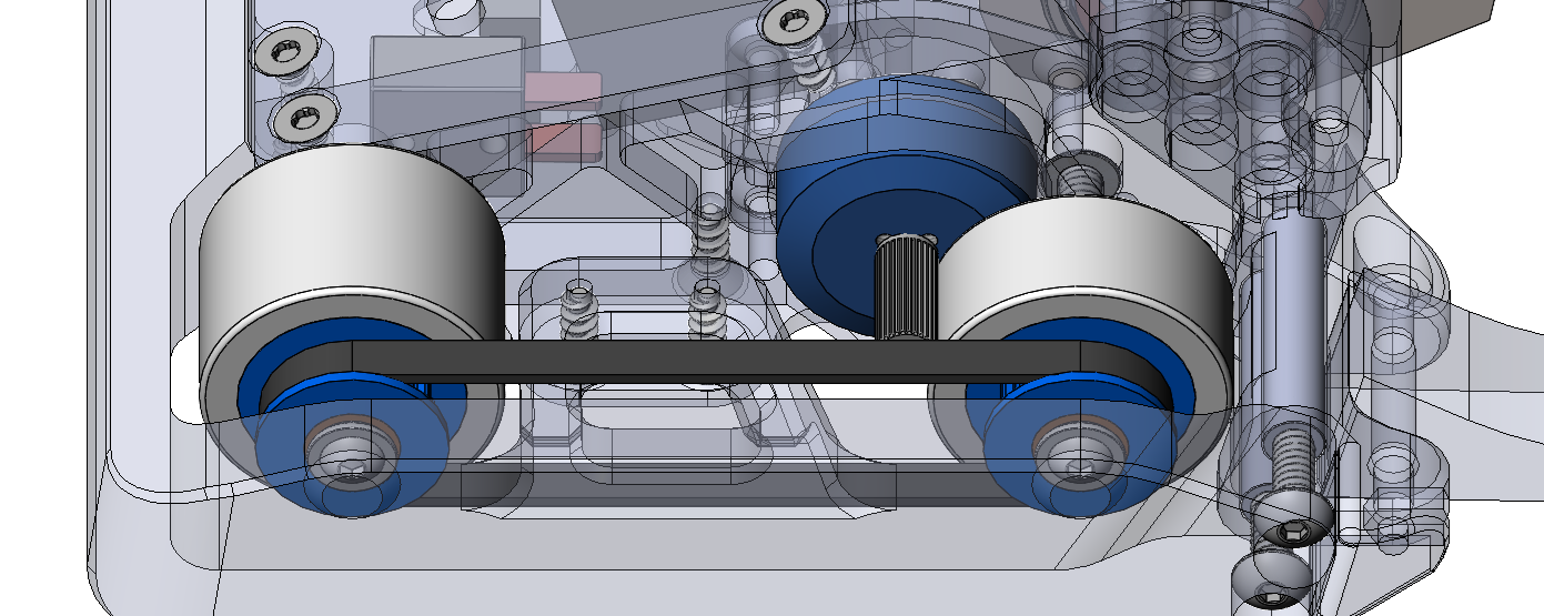
Hub motor drum design
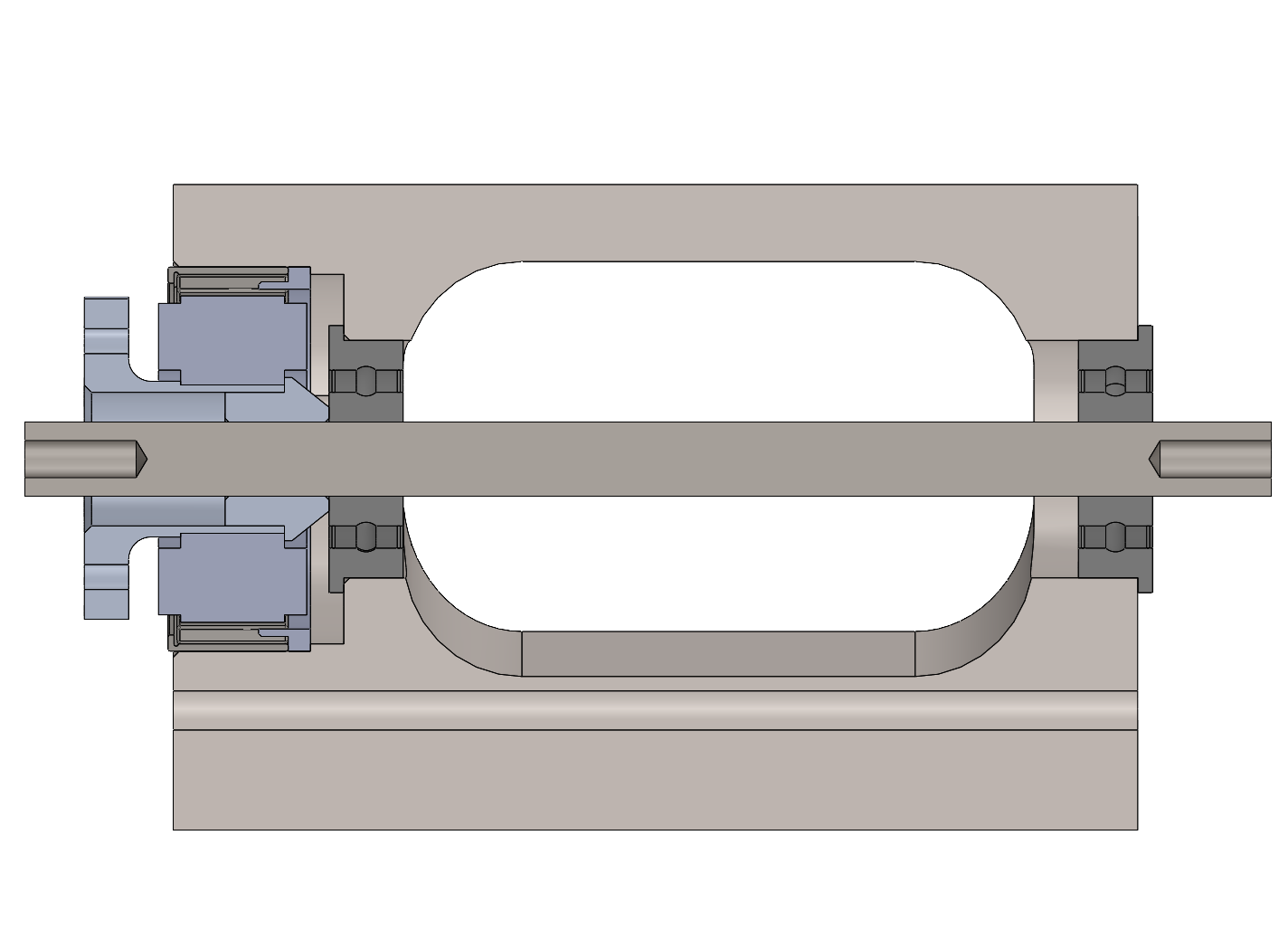
Section View
After competing with this iteration, I still found problems.
1. The vibration issue had improved, but it was still causing issues with driving. Why? Upon spinning by hand, there was no unevenness indicating bearing misalignment. It seemed like a balance issue, as it was worse with higher weapon speeds, but I had already verified the weapon center of mass was at (0,0). After some thinking, I realized I had considered static balance, but not dynamic balance.
Although the center of mass was at (0,0), spinning the weapon up would create a torque that twists the drum off axis due to an imbalance of the centrifugal forces imparted on the drum. Essentially, all the forces cancel, but not all the moments generated by these forces!
I verified this theory by setting up a solidworks motion study in which the drum spins on its axis, and the reaction force at its bearing supports is recorded. If the drum is fully balanced, this value should be 0.
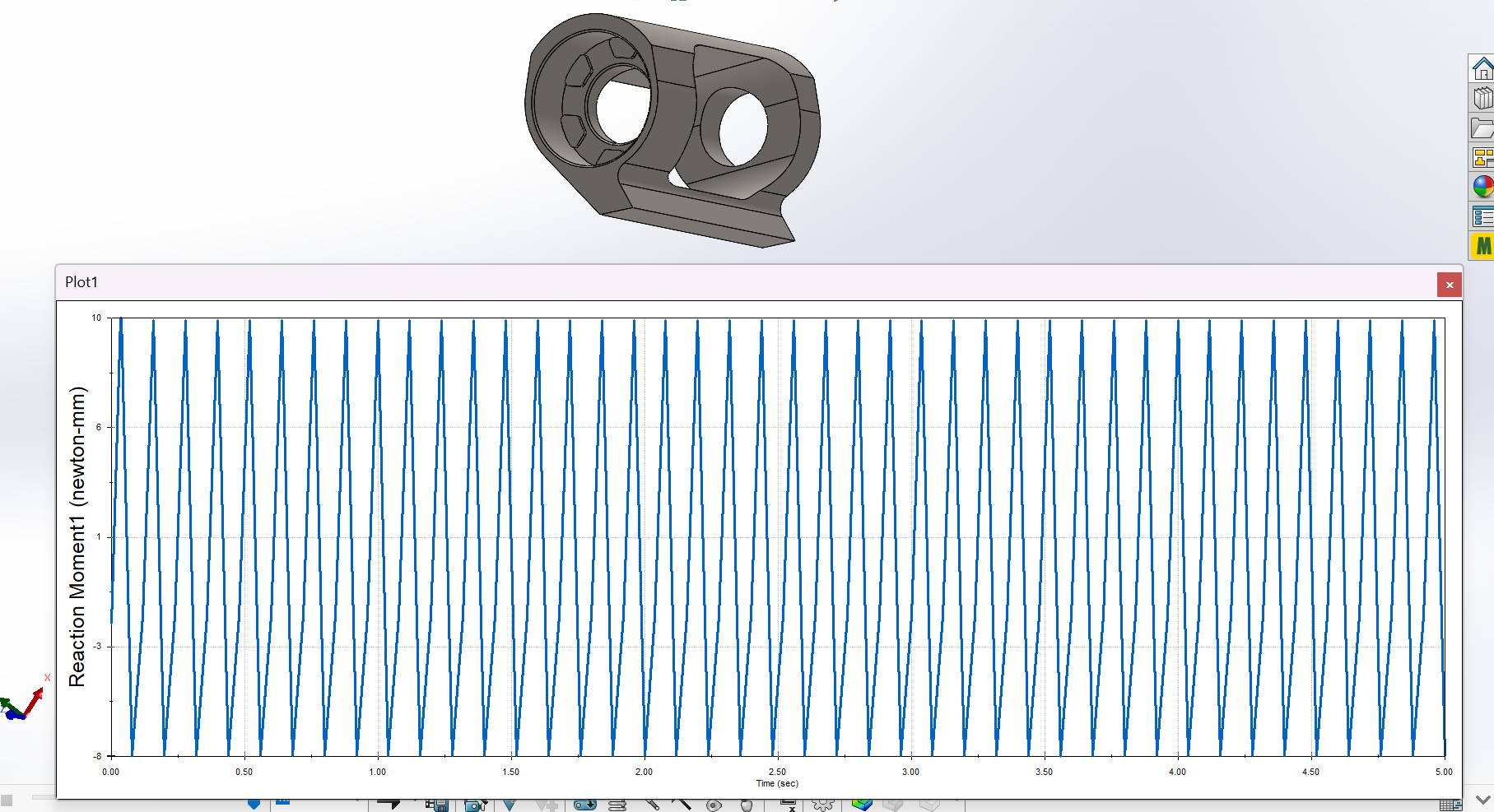
Reaction moment graph at bearing support showing imbalance
And as we see from the motion study, that is not the case! The peaks and valleys of this are also in sync with the rotation frequency.
Just to help validate that what I was seeing was real, I checked a completely symmetric drum design, which gave us a positive result: almost 0 reaction force.
I addressed this by making a tweak to the drum design. I made sure that the cross section of the drum profile itself was statically balanced. Then the weight reduction hole in the middle kept this balance throughout the drum. I checked this design in simulation as well, and the reaction force was reduced to nearly 0.
2. Magnets were still breaking. I suspected this is due to a suuuper tight air-gap between the rotor and the stator as measured, it was would 0.1mm! Drone motors achieve small air gaps because it improves power output, but in my case, it made it very likely for the magnets to collide with the stator if there was any deflecction in the system (which there is bound to be when dealing with high impact loads).
To address this, I was able to source a different magnet ring of similar size with larger air-gap (0.25 vs 0.1mm).
I recompeted with this improved drum design. Many of the problems had been resolved! The drum was more durable, and most importantly, wasn't vibrating my robot all over the place. With these improvements, I was able to snag a 3rd place victory. Although this solved a lot of problems, I was still breaking magnets! At this point in time, I have no confirmed solution yet... but I am planning to make some changes to the hub motor structure to place bearing supports on either side of the stator to helpfully completely eliminate rotor deflection into the stator causing the magnets to crack. Stay tuned!
Drivetrain Improvements
Problem: V1 made use of an over-sized drive motor combined with a custom 2-stage 8:1 gearing to the wheels compared to a traditional motor + planetary gearbox combo. This provided excellent drive power and speed and a convenient packaging shape. However there were some problems.
- Intermediate drive gear needed to achieve enough reduction resulted in additional complexity, longer repair times, and additional failure points
- Package space required was relatively large, which increased drivetrain weight
Moonshot's V1 drive components. Pretty to look at, but more complex than necessary.
To solve this, I decided to package as much reduction as possible into a single drive stage. This would completely eliminate the secondary reduction stage and remove the intermediate drive gear, saving space, weight, complexity, and improving reliability.
With a traditional gear drive, I was limited by the size of the motor pinion gear. Too small, and the teeth would be so fine that I could not rely on them to mesh consistently, and would require precise gear teeth + alignment that I could not guarentee in a combat environment. Too large, and there simply wouldn't be enough reduction, and the ESC would struggle with the high-startup torque needed to start the brushless drive motors.
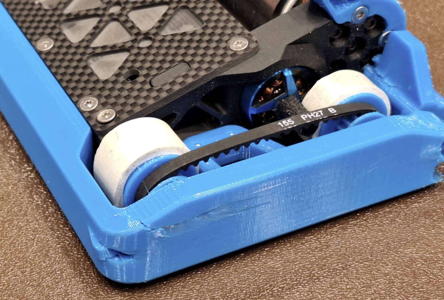
A "tangent-drive" was the solution. This drive system uses a roller which contacts the outside of the wheel via friction. This nets you as much reduction as possible in a single stage, and eliminates the need for gear teeth meshing. Instead, I can design for a certain amount of "squish" to make sure the roller makes good contact with soft surface of the wheel.
Moonshot's V2 drive components. Note the small package and simplicity!
When selecting a motor I looked for a low KV, as it would result in better control at full throttle.
When designing the first draft of the robot, I planned for the tangent drive rollers to press onto the motor shaft and be machined from aluminum. As a test, I 3D printed a prototype and fit it to the motor. The plastic press-fit seemed to hold quite well, and after seeing the cost of having these parts made from metal, I doubled down on the plastic design. I added pegs to interface with the motor mounting holes to help transfer torque better, and developed a small fixture to help me press on the rollers using a vise.
This drivetrain was trialed in the first 3D printed iteration of this robot, which competed in the "plastic" antweight category. I used this first prototype to trial some different options regarding the needed amount of wheel compression. Additionally, I made use of the "fuzzy skin" print setting to add some roughness to the outside of the roller, improving the coefficient of friction between the wheel and the roller.
I identified the following issues after this competition:
- Insufficient wheel - roller contact due to insufficent mounting stiffness
- Motor heat caused softening of the plastic mounting, causing the motor to flex away
For the full-combat design, I could fix these problems. I replaced the plastic mounting with a carbon fiber mounting plate which was much stiffer while remaining light. Additionally, since it is not a thermoplastic, I did not have to worry about the material softening and creeping over time.
Since making these improvements, the tangent drive system has been robust with no unpreventable failures, and the design has remained largely unchanged throughout a few iterations. I consider the current design a success.
However, this design has increased in popularity since my initial design, and off-the-shelf products exist which are designed for tangent drive applications with a number of benefits which my design could not achieve without extensive cost/modification of the motor. Although i'm proud of my current implementation, I'll be evaluating and considering the off-the shelf solutions in the future.
Chassis Improvements
Moonshot Chassis
Moonshot side view
Throughout the many fights the original design had, I identified a number of areas for improvement: - opponents could sometimes punch through the squishy TPU side armor and hit important drivetrain components - 3D printed uprights lacked impact toughness - rear was vulnurable to attacks - difficulty of service and assembly due to screw positions
I sought to improve the armor package by isolating the outer armor as much as possible from the critical parts of the robot. The philosophy that I have been following for the robots I design is as follows: The armor shall be able to be completely destroyed or removed without hampering any critical functions (drive or weapon). I implemented a similar flexible TPU armor strategy as moonshot V1, but I focused on making the armor beefier, with a wraparound feature protecting the rear (at the cost of wheel contact when the bot is tilted). The whole armor piece is a single printed TPU component, which reduces part count and also reduces risk of the armor pieces tearing apart from their fastener connections. I also redesigned the drive system to use a fully cantilevered design, and redesigned the side armor with an air-gap to the drive components. I also designated a side mounting point independent of any critical mounting structure. This side mounting point is designed to be flexible to prevent significant load transfer to the rest of the chassis.
This redesigned armor has proven to be extremely effective, absorbing hits and leaving minimal damage to the rest of the robot.
Wraparound TPU wheelguards effectively protecting drive components from dadmage
One of the latest improvements that was made in the past few months was moving to UHMW-PE instead of 3d printed PLA+ for the main chassis rails. UHMWPE is an excelent choice do to having very good impact properties, and also low density compared to other plastics. Additionally, it avoids the delamination issues that can come with 3D printed parts.